Gift wrapping algorithm

In electronics or EET, a voltage divider (also known as a potential divider) is a linear circuit that produces an output voltage (Vout) that is a fraction of its input voltage (Vin). Voltage division refers to the partitioning of a voltage among the components of the divider.
An example of a voltage divider consists of two resistors in series or a potentiometer. It is commonly used to create a reference voltage, or to get a low voltage signal proportional to the voltage to be measured, and may also be used as a signal attenuator at low frequencies. For direct current and relatively low frequencies, a voltage divider may be sufficiently accurate if made only of resistors; where frequency response over a wide range is required (such as in an oscilloscope probe), the voltage divider may have capacitive elements added to allow compensation for load capacitance. In electric power transmission, a capacitive voltage divider is used for measurement of high voltage.
General case
A voltage divider referenced to ground is created by connecting two electrical impedances in series, as shown in Figure 1. The input voltage is applied across the series impedances Z1 and Z2 and the output is the voltage across Z2. Z1 and Z2 may be composed of any combination of elements such as resistors, inductors and capacitors.
Applying Ohm's Law, the relationship between the input voltage, Vin, and the output voltage, Vout, can be found:
Proof:
The transfer function (also known as the divider's voltage ratio) of this circuit is simply:
In general this transfer function is a complex, rational function of frequency.
Examples
Resistive divider

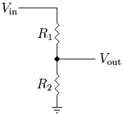
A resistive divider is the case where both impedances, Z1 and Z2, are purely resistive (Figure 2).
Substituting Z1 = R1 and Z2 = R2 into the previous expression gives:
If R1 = R2 then
If Vout=6V and Vin=9V (both commonly used voltages), then:
and by solving using algebra, R2 must be twice the value of R1.
To solve for R1:
To solve for R2:
Any ratio Vout/Vin greater than 1 is not possible. That is, using resistors alone it is not possible to either invert the voltage or increase Vout above Vin.
Low-pass RC filter

Consider a divider consisting of a resistor and capacitor as shown in Figure 3.
Comparing with the general case, we see Z1 = R and Z2 is the impedance of the capacitor, given by
where XC is the reactance of the capacitor, C is the capacitance of the capacitor, j is the imaginary unit, and ω (omega) is the radian frequency of the input voltage.
This divider will then have the voltage ratio:
The product τ (tau) = RC is called the time constant of the circuit.
The ratio then depends on frequency, in this case decreasing as frequency increases. This circuit is, in fact, a basic (first-order) lowpass filter. The ratio contains an imaginary number, and actually contains both the amplitude and phase shift information of the filter. To extract just the amplitude ratio, calculate the magnitude of the ratio, that is:
Inductive divider
Inductive dividers split AC input according to inductance:
The above equation is for non-interacting inductors; mutual inductance (as in an autotransformer) will alter the results.
Inductive dividers split DC input according to the resistance of the elements as for the resistive divider above.
Capacitive divider
Capacitive dividers do not pass DC input.
For an AC input a simple capacitive equation is:
Any leakage current in the capactive elements requires use of the generalized expression with two impedances. By selection of parallel R and C elements in the proper proportions, the same division ratio can be maintained over a useful range of frequencies. This is the principle applied in compensated oscilloscope probes to increase measurement bandwidth.
Loading effect
The voltage output of a voltage divider is not fixed but varies according to the load. To obtain a reasonably stable output voltage the output current should be a small fraction of the input current. The drawback of this is that most of the input current is wasted as heat in the divider. An alternative is to use a voltage regulator.
Applications
Voltage dividers are used for adjusting the level of a signal, for bias of active devices in amplifiers, and for measurement of voltages. A Wheatstone bridge and a multimeter both include voltage dividers. A potentiometer is used as a variable voltage divider in the volume control of a radio. Voltage dividers can also be used to allow a microcontroller to measure the resistance of a sensor.[1] The sensor is hooked up in a voltage divider alongside a known resistor, and a known input voltage is given, and the output voltage is measured, and then used to determine the resistance of the sensor.
References
43 year old Petroleum Engineer Harry from Deep River, usually spends time with hobbies and interests like renting movies, property developers in singapore new condominium and vehicle racing. Constantly enjoys going to destinations like Camino Real de Tierra Adentro.
Further reading
- 20 year-old Real Estate Agent Rusty from Saint-Paul, has hobbies and interests which includes monopoly, property developers in singapore and poker. Will soon undertake a contiki trip that may include going to the Lower Valley of the Omo.
My blog: http://www.primaboinca.com/view_profile.php?userid=5889534
See also
External links
- Voltage divider and current calculator with variable count of resistors
- Voltage divider or potentiometer calculations
- Voltage divider tutorial video in HD
- Online calculator to choose the values by series E24, E96
- Online voltage divider calculator: chooses the best pair from a given series and also gives the color code
- Java based search tool for analysing a potential divider circuit
- Voltage divider theory - RC low-pass filter example and voltage divider using Thévenin's theorem


